
Building my own camera
August 2026 · 4 min read
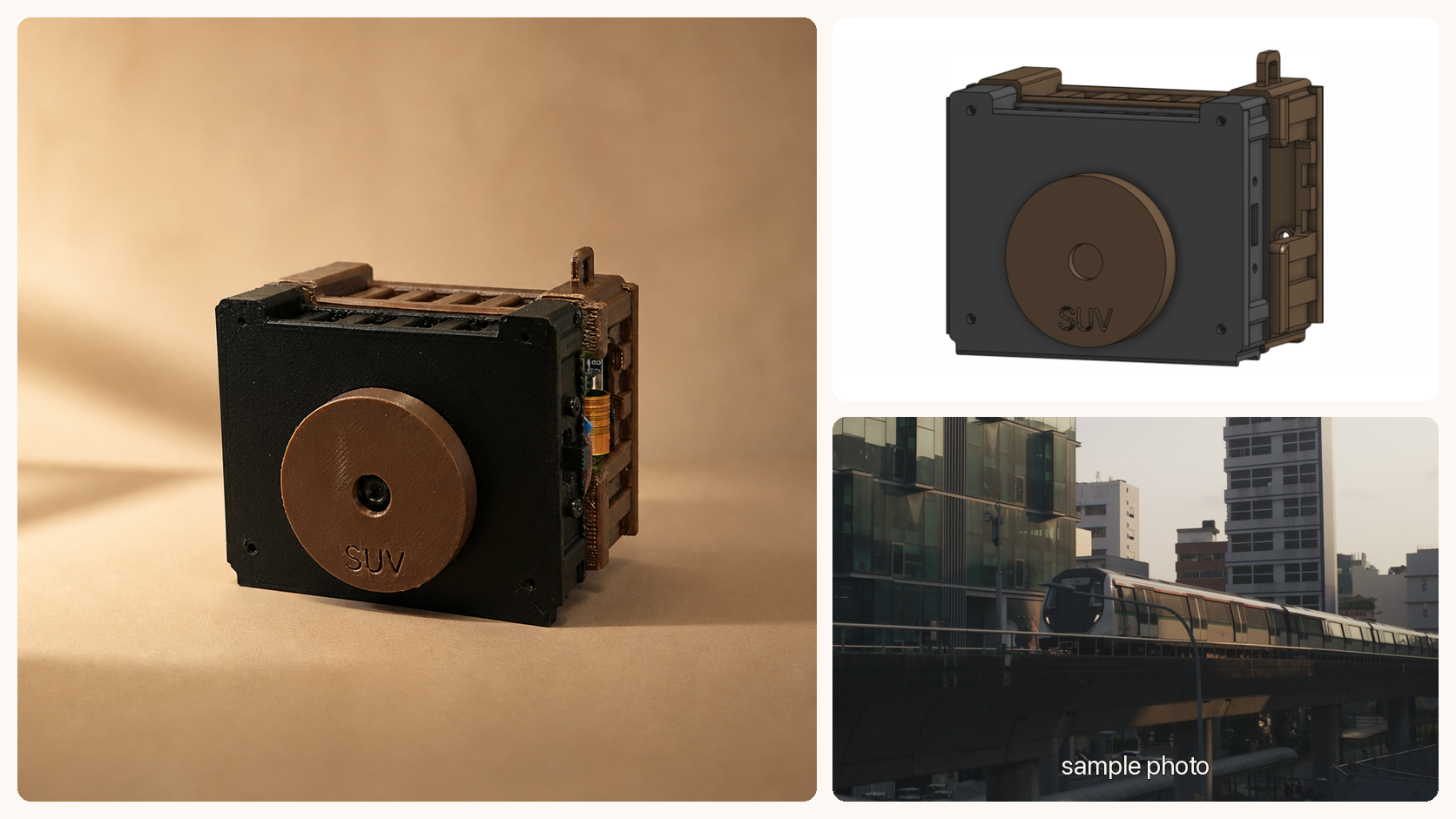
I have always been fascinated by digital cameras that give photos a film-like look. You get a nice warm image without having to develop film. In 2023, I bought a Papershoot camera, a tiny DIY digital camera, and kept using it even with the lower resolution.
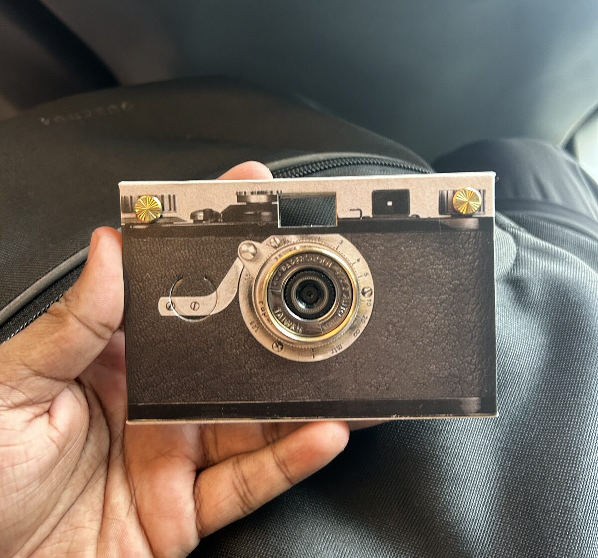
I used to take photos with it whenever we hosted dinners at our house in the US. My friends would tell guests I had built the camera myself. It looked distinctive enough to make the story believable, and they would start asking me questions. I never corrected them right away haha.
Funnily enough, the idea of building my own camera resurfaced in my head recently. Other than this being a cool project, this time there was another reason. A couple of months ago, at AI Engineer Singapore, I talked about working across the full robotics stack, and how valuable cross-domain knowledge is. That range is what makes problems get solved faster.
I thought this would be a great way to get more hands-on with hardware.
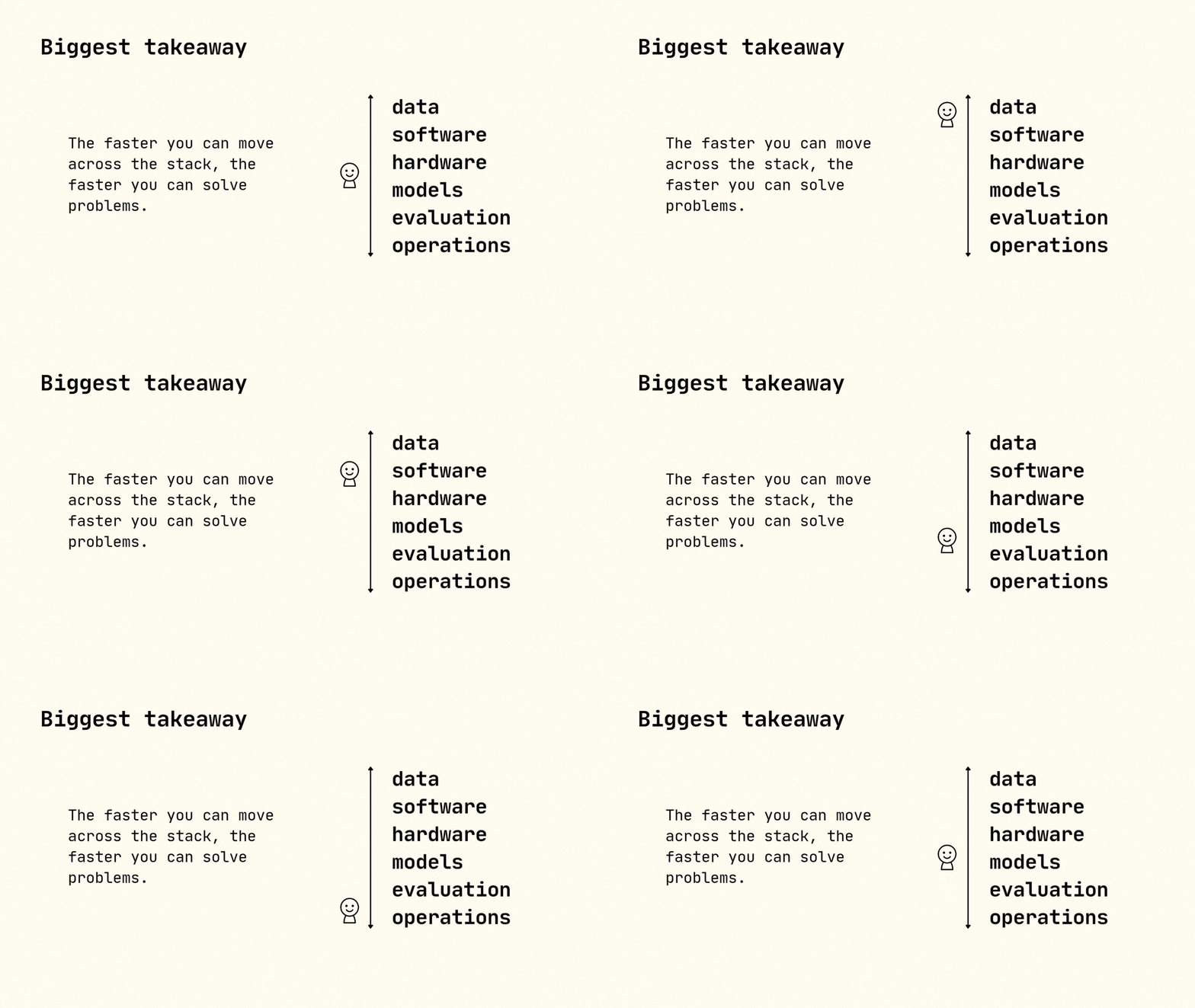
Final slide from my speech at AI Engineer Singapore 2026
So I decided to build my own Tiny Film Camera.
I looked up custom-made cameras and read through a few interesting projects: Volzo's Digital Toy Camera, Dora Goodman, and a YouTube short by mewtru, to name a few.
Once I settled on the bill of materials (BOM) and the parts arrived, I quickly got to a place where the Raspberry Pi Zero 2W was on my phone's hotspot, and I could test the camera through a small web app.
The main thing I wanted was the filmy look. Straight out of the Camera Module 3, the photos were very clean and very digital. To get the photos to look the way I wanted, I had to take it out for testing in different light settings even before it was fully assembled. In hindsight, I should have built a simple enclosure to make the testing process smoother.
Once the software side of things was sorted, I started on the design. For a quick turnaround, I looked up existing printable Raspberry Pi and Waveshare UPS cases on Printables.
I tried vibe-CADing the spacers with Claude Code to hold the layers together. It only got me a few C-shaped brackets in 20 mm and 25 mm sizes, which I tried with different hole diameters. After a few iterations on the brackets, I put together a functional v0.
The v0 build left plenty exposed. You could see the wiring and the stacked cases, and the shutter button sat out on top with a cable tie. But it did feel like I was holding a camera.
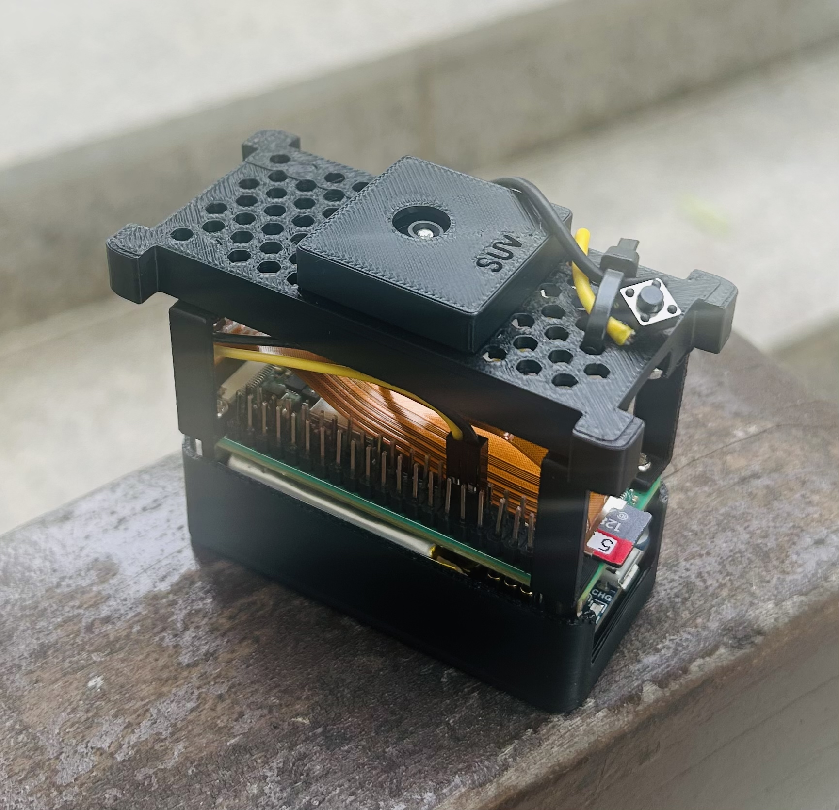
v0
I took this version to my graduation ceremony and took photos, but I didn't quite like the feel of it, so I decided to iterate and come up with a better design.
I started learning Onshape, an online CAD tool, and designed all the components from scratch. I ended up printing multiple versions, mostly because I did not leave enough tolerance around the mounting holes. You can find all the final CAD files here.
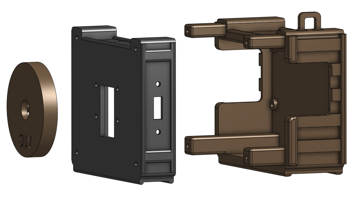
v1 CAD
Designing the v1 enclosure in Onshape
Once the prints fit, I moved on to assembly. This phase was particularly fun. I got to revisit soldering from uni days, and pick up new things like heat-set inserts. I soldered the components, wired them up, and sanded the slider until it sat right. I can proudly say I can look at a screw or a nut now and tell which size it is, pretty accurately.
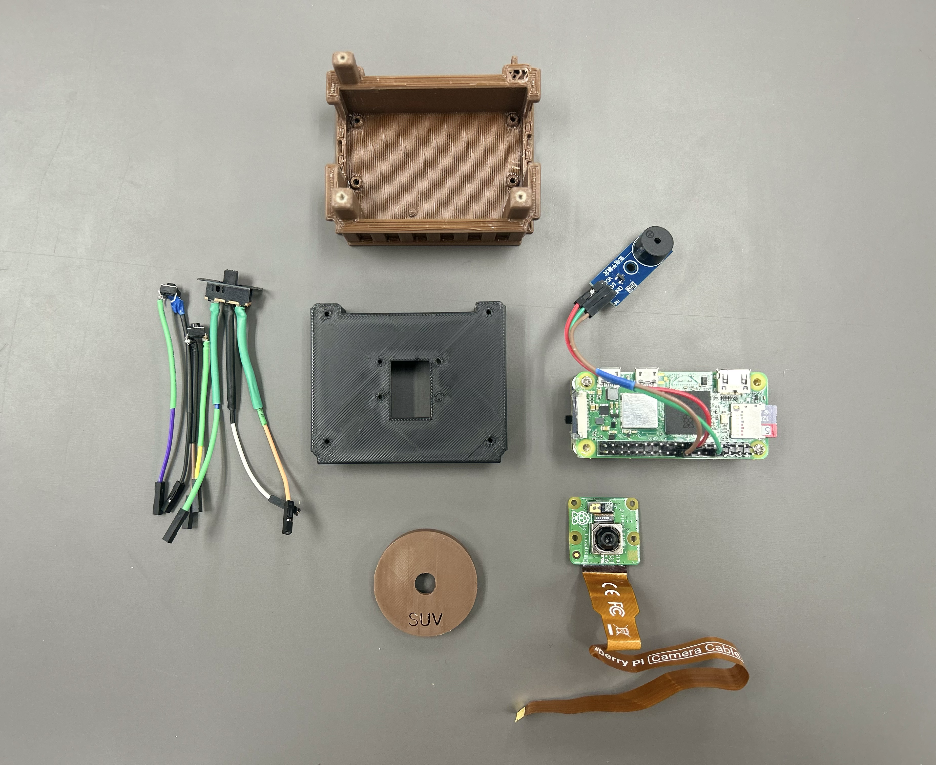
Components
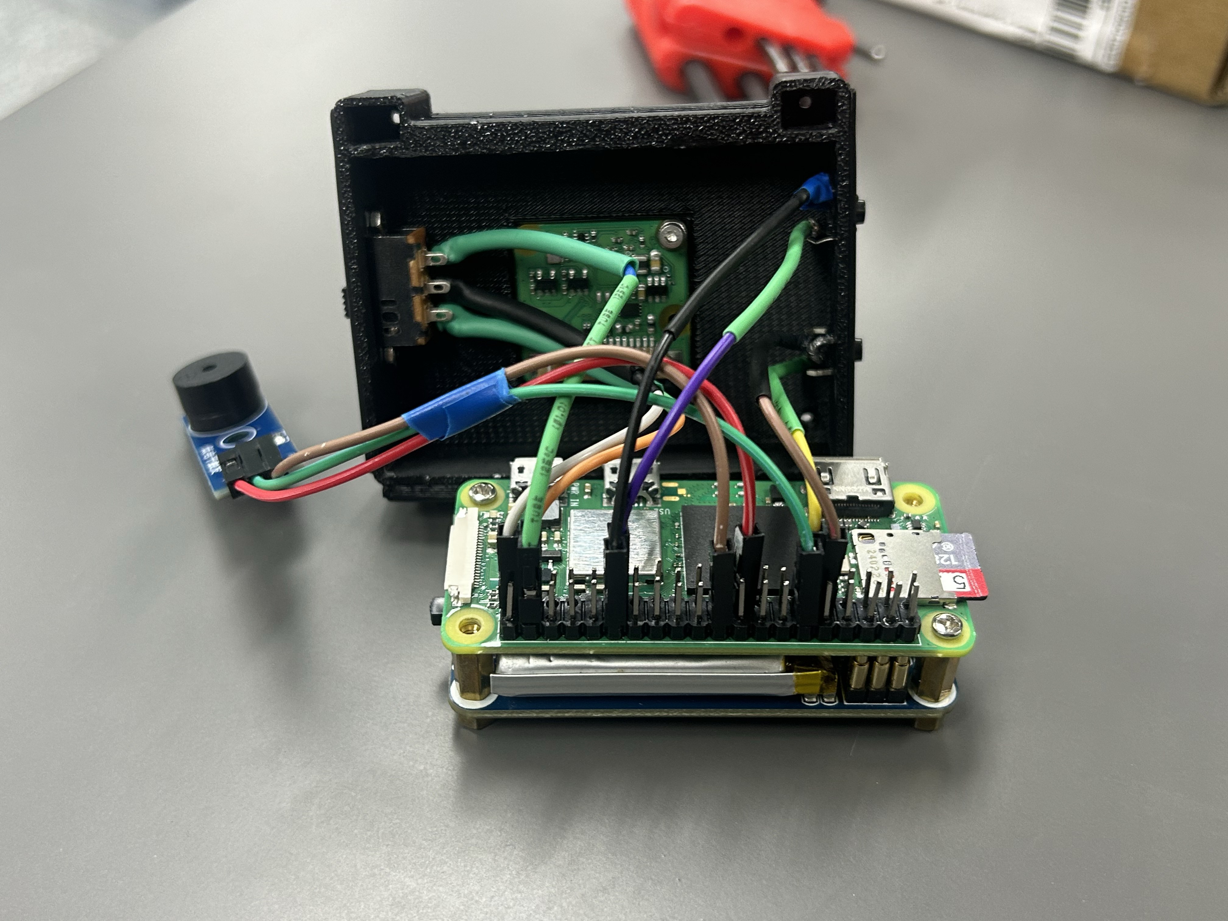
Wiring
The final version has a video recording option with its own button, and a slider switch that lets me pick one of the three filters I added. I also addressed two obvious gaps. I could not tell when it had started, or when a photo had actually been taken. A passive buzzer closed that loop.
I still did not put a screen on it. The Pi runs a small local web app instead. When the camera joins my phone hotspot, I can open the gallery, see recent photos and videos, download them, or delete the obvious misses. The page also shows the battery level, so I know when it needs to be charged.
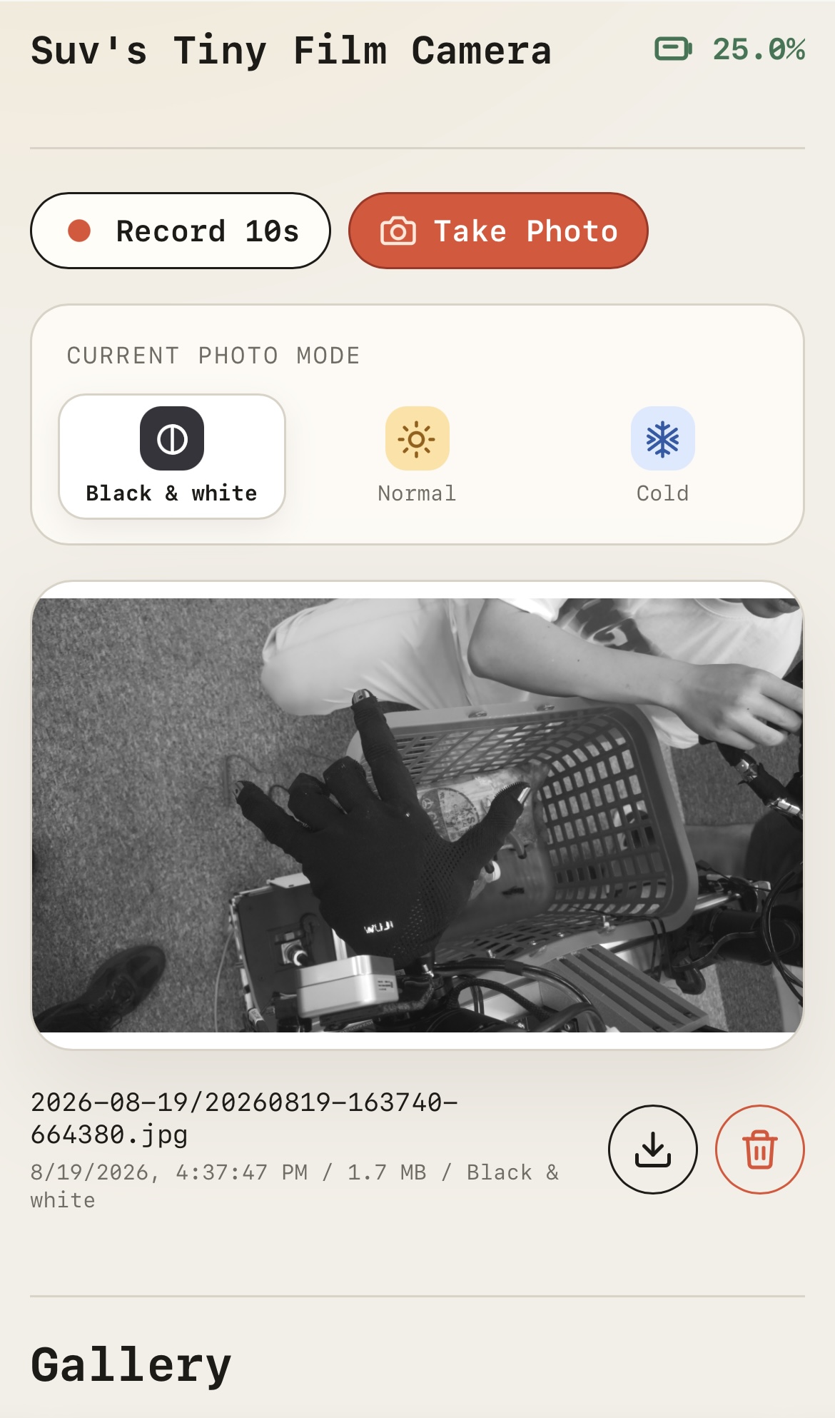
Web app
Now I can finally say I actually built a camera!
You can find the code and CAD on GitHub. Thank you for reading.